Ed Yaris, Manufacturing Engineer, Lowell Inc.08.11.20
There are a number of tools in a manufacturer’s toolbox to measure and inspect devices and components. Some of these tools are equipment and machines, such as calipers or coordinate measuring machines (CMMs), and software for analysis and reporting. Others are methods like profile tolerancing and geometric dimensioning and tolerancing (GD&T).
With any project, certain tools work better than others for specific tasks. The more complex a device’s geometry or part becomes, the more specialized the machines and methods should become.
The basics of profile tolerancing and GD&T are well known in the industry, but the techniques haven’t been broadly adopted as a way to communicate design intent. The traditional method of linear plus/minus (±) dimensioning continues to be the leading approach for communicating tolerances and dimensions in a drawing.
As manufacturers review their customers’ drawings and prepare to machine, inspect, and measure a part, some turn to profile tolerancing to clear up any ambiguity and improve the end result. If your manufacturer recommends creating a version of your drawing in profile, there are a number of reasons to consider it—especially to save critical time during inspection and reduce the risk of repeat measurement.
Comparing Profile Tolerancing and Linear ± Dimensioning
Profile tolerancing is part of GD&T. It defines uniform upper- and lower-level boundaries around the desired physical nominal geometry. It takes into account orientation and location, as well as size and form. This is especially effective for complex features of medical devices, which require rigorous inspection, because it leads to more efficient, effective measurement and quality control. Compared to linear dimensions, the tolerancing scheme and inspection requirements are much simpler.
Drawings with linear ± dimensioning require the inspection of each feature for size, form, orientation, or location. A single feature can have several inspectable dimensions. Each dimension may also require a different inspection method. The inspection process can be very time consuming, affecting timelines and adding significant cost.
As a comparison of these two methods, a drawing may show a feature with an allowable tolerance in size of ±0.1 mm. An example would be a thru hole that would require size, locations, and form. To communicate that with linear dimensioning, there could be several different dimensions used, which would then require individual inspection. Up to five independent dimensions that describe the thru hole can be replaced with one profile. With profile tolerancing, the tolerance is described as “0.1 mm all around.” The inspection process captures hundreds of data points to describe the surface of the thru hole and each data point is compared to the nominal CAD geometry.
Reducing the Risk of Repeat Measurement
Since profile tolerancing can remove ambiguity in a drawing, it can also help the measurement process run more smoothly. All inspection CMMs have some inaccuracy potential. If the point of measurement isn’t appropriately square, perpendicular, or parallel, that single point can skew the entire result.
When a measurement is out of tolerance, it means the part needs to be measured again, and often a third time. If the first measurement shows the part is out of tolerance, and the second shows it within tolerance, a third measurement should be taken to confirm which is correct. When there are multiple dimensions to verify, this can lead to longer measurement times.
For some geometric features, linear ± tolerancing requires measured points from a CMM to be constructed into geometric shapes to meet the drawing requirements. Small deviations in location—such as measured points of complex geometries, short surface features and small arc radii—may significantly affect the calculated result. These inaccuracies can lead to accepting nonconforming components or rejecting conforming components.
Profile tolerancing uses the location of each measured X, Y, and Z point relative to the CAD model’s nominal geometry to determine the condition of the measured part or feature. This can eliminate some of the risk of inaccuracy seen with linear ± tolerancing.
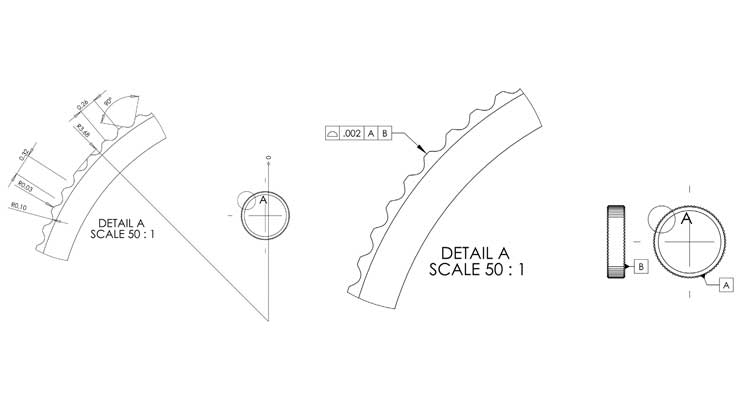
Figure 1 depicts the detail of small arc radii using a linear ± dimensioned drawing and a drawing using profile tolerancing. The linear ± dimensioned drawing on the left has over seven depicted features or dimensions to define the size, form, orientation, and location of the small arc radii, and allows for possible misinterpretation of design intent.
On the right, the profile drawing uses all the data points from the original CAD model, and the small arc radii features are depicted as a profile of a surface with control of “0.002 inch all around.” All this is depicted by the simple directions stated in the feature control frame.
Reducing Inspection Time
Another benefit of profile tolerancing over linear ± dimensioning is time saved on dimensioning the drawing and inspection. A cervical plate is a good example of the potential time savings, as seen in Table 1. Compared to linear ± dimensioning, profile tolerancing can cut the estimated dimensioning time required by more than half, in this case from 480 minutes to 180.
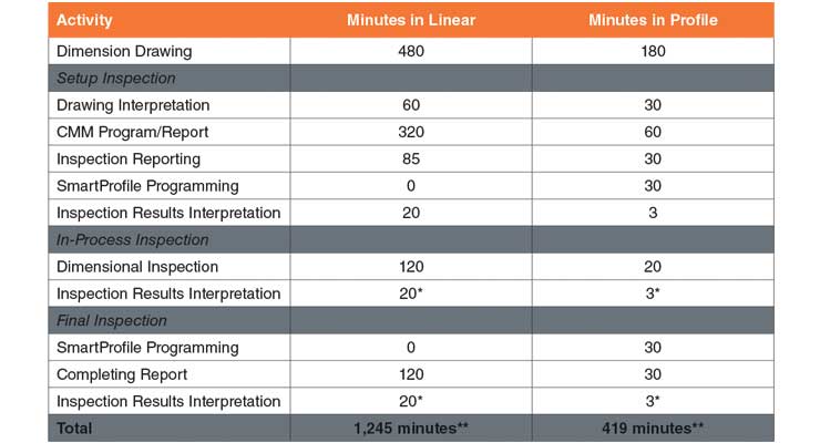
Table 1: Comparing time estimates for dimensioning and inspection in linear ± dimensioning vs. profile tolerancing.
* These numbers represent the minimum time estimates based on one inspection results interpretation. Depending on the product, this process may repeat often during in-process and final inspection.
** These totals are based on the minimum time required for inspection results interpretation.
Profile tolerancing can also reduce the amount of time it takes a manufacturer to complete setup, in-process, and final inspection.
Setup inspection verifies the first part in a lot created by the manufacturing process conforms to the drawing requirements. It is an essential first step to ensure the process is set up correctly, and devices and components will be made accurately. Any adjustments to the machining process will be made based on this inspection, so accuracy is critical.
In the cervical plate example, there is a dramatic difference in setup inspection time, with profile eliminating more than 330 minutes from the linear ± dimensioning process. This is because there is only one measurement result to inspect, rather than multiple with linear dimensioning.
In-process inspection ensures the manufacturing process that was verified in setup inspection is maintained throughout production. Devices coming off the line are checked at intervals to ensure process stability.
With traditional linear ± tolerancing, a machinist or quality engineer has to scan lines of dimensions and measurements on a printout and compare back to a drawing to see if there is any deviation. Reports can be as large as 20 pages if there are multiple critical dimensions. This creates the need for the machinist and inspector to review potentially hundreds of dimensions printed in excruciating detail. While this mountain of data is reviewed, parts continue to be made. This creates a potential gap between identifying an error and removing nonconforming parts from the line.
This gap is reduced with profile tolerancing, which provides visual feedback of an inspected part via a 3D CAD model. A machinist can see at a glance if a dimension or feature is nonconforming, decreasing the time between identifying an error and halting production to amend the process. The example in Table 1 shows the difference: 120 minutes in linear vs. 20 minutes in profile for dimensional inspection, with an additional 17 minutes saved per round of inspection results interpretation.
The typical final inspection process for medical devices requires the review of a random sample of the lot to ensure the products are made correctly and conform to requirements. Statistical sampling tables determine the quantity of parts needed for testing. These tables are based on acceptance sampling, which indicates how many products need to be reviewed to reliably predict an entire batch conforms to requirements.
Measurement, testing, and inspection of final elements traditionally would be completed manually against linear measurements. That data is then used to create the associated inspection report paperwork. This entire process is greatly improved through CMM technology. Instead of manually preparing an inspection report, CMM data is printable for use in the report, and can be submitted for external review. In the example from Table 1, the time savings in the final inspection stage showed a total reduction of inspection time by 60 minutes when using profile, with an additional 17 minutes saved per round of inspection results interpretation.
Medical device companies have also seen that project data from profile tolerancing streamlines their internal acceptance process. A manufacturer will compile the profile data into a project file that’s shared with the customer. This firsthand data can be reviewed in much less time than traditional linear ± data.
Partnering with the Contract Manufacturer
Profile tolerancing has come a long way in the past several years, with new software that can automate much of the analysis process. While your company may not have this software, many contract manufacturers have invested in this technology to improve their measurement, inspection, and quality capabilities, as well as their customers’ device results. New measurement machines are increasingly evolving to include their own profile analysis software, too.
A contract manufacturer may recommend creating a version of the drawing that uses profile tolerancing, which they can then use for machining and inspection. This is typically managed via a change order or waiver, without changing the original drawing or design intent.
By exploring the different ways profile tolerancing can clarify a drawing and design intent, medical device firms may find new ways to improve inspection time, measurement time, and results.
Ed Yaris is a manufacturing engineer at Lowell with extensive experience in metrology, management, and CMM software development. He's held leadership positions at National Security Technologies, Helmel Engineering Products, Renishaw, and GE. In addition, Yaris is a member in good standing of twelve ASME/B89 standards committees.
With any project, certain tools work better than others for specific tasks. The more complex a device’s geometry or part becomes, the more specialized the machines and methods should become.
The basics of profile tolerancing and GD&T are well known in the industry, but the techniques haven’t been broadly adopted as a way to communicate design intent. The traditional method of linear plus/minus (±) dimensioning continues to be the leading approach for communicating tolerances and dimensions in a drawing.
As manufacturers review their customers’ drawings and prepare to machine, inspect, and measure a part, some turn to profile tolerancing to clear up any ambiguity and improve the end result. If your manufacturer recommends creating a version of your drawing in profile, there are a number of reasons to consider it—especially to save critical time during inspection and reduce the risk of repeat measurement.
Comparing Profile Tolerancing and Linear ± Dimensioning
Profile tolerancing is part of GD&T. It defines uniform upper- and lower-level boundaries around the desired physical nominal geometry. It takes into account orientation and location, as well as size and form. This is especially effective for complex features of medical devices, which require rigorous inspection, because it leads to more efficient, effective measurement and quality control. Compared to linear dimensions, the tolerancing scheme and inspection requirements are much simpler.
Drawings with linear ± dimensioning require the inspection of each feature for size, form, orientation, or location. A single feature can have several inspectable dimensions. Each dimension may also require a different inspection method. The inspection process can be very time consuming, affecting timelines and adding significant cost.
As a comparison of these two methods, a drawing may show a feature with an allowable tolerance in size of ±0.1 mm. An example would be a thru hole that would require size, locations, and form. To communicate that with linear dimensioning, there could be several different dimensions used, which would then require individual inspection. Up to five independent dimensions that describe the thru hole can be replaced with one profile. With profile tolerancing, the tolerance is described as “0.1 mm all around.” The inspection process captures hundreds of data points to describe the surface of the thru hole and each data point is compared to the nominal CAD geometry.
Reducing the Risk of Repeat Measurement
Since profile tolerancing can remove ambiguity in a drawing, it can also help the measurement process run more smoothly. All inspection CMMs have some inaccuracy potential. If the point of measurement isn’t appropriately square, perpendicular, or parallel, that single point can skew the entire result.
When a measurement is out of tolerance, it means the part needs to be measured again, and often a third time. If the first measurement shows the part is out of tolerance, and the second shows it within tolerance, a third measurement should be taken to confirm which is correct. When there are multiple dimensions to verify, this can lead to longer measurement times.
For some geometric features, linear ± tolerancing requires measured points from a CMM to be constructed into geometric shapes to meet the drawing requirements. Small deviations in location—such as measured points of complex geometries, short surface features and small arc radii—may significantly affect the calculated result. These inaccuracies can lead to accepting nonconforming components or rejecting conforming components.
Profile tolerancing uses the location of each measured X, Y, and Z point relative to the CAD model’s nominal geometry to determine the condition of the measured part or feature. This can eliminate some of the risk of inaccuracy seen with linear ± tolerancing.
Figure 1 depicts the detail of small arc radii using a linear ± dimensioned drawing and a drawing using profile tolerancing. The linear ± dimensioned drawing on the left has over seven depicted features or dimensions to define the size, form, orientation, and location of the small arc radii, and allows for possible misinterpretation of design intent.
On the right, the profile drawing uses all the data points from the original CAD model, and the small arc radii features are depicted as a profile of a surface with control of “0.002 inch all around.” All this is depicted by the simple directions stated in the feature control frame.
Reducing Inspection Time
Another benefit of profile tolerancing over linear ± dimensioning is time saved on dimensioning the drawing and inspection. A cervical plate is a good example of the potential time savings, as seen in Table 1. Compared to linear ± dimensioning, profile tolerancing can cut the estimated dimensioning time required by more than half, in this case from 480 minutes to 180.
Table 1: Comparing time estimates for dimensioning and inspection in linear ± dimensioning vs. profile tolerancing.
* These numbers represent the minimum time estimates based on one inspection results interpretation. Depending on the product, this process may repeat often during in-process and final inspection.
** These totals are based on the minimum time required for inspection results interpretation.
Profile tolerancing can also reduce the amount of time it takes a manufacturer to complete setup, in-process, and final inspection.
Setup inspection verifies the first part in a lot created by the manufacturing process conforms to the drawing requirements. It is an essential first step to ensure the process is set up correctly, and devices and components will be made accurately. Any adjustments to the machining process will be made based on this inspection, so accuracy is critical.
In the cervical plate example, there is a dramatic difference in setup inspection time, with profile eliminating more than 330 minutes from the linear ± dimensioning process. This is because there is only one measurement result to inspect, rather than multiple with linear dimensioning.
In-process inspection ensures the manufacturing process that was verified in setup inspection is maintained throughout production. Devices coming off the line are checked at intervals to ensure process stability.
With traditional linear ± tolerancing, a machinist or quality engineer has to scan lines of dimensions and measurements on a printout and compare back to a drawing to see if there is any deviation. Reports can be as large as 20 pages if there are multiple critical dimensions. This creates the need for the machinist and inspector to review potentially hundreds of dimensions printed in excruciating detail. While this mountain of data is reviewed, parts continue to be made. This creates a potential gap between identifying an error and removing nonconforming parts from the line.
This gap is reduced with profile tolerancing, which provides visual feedback of an inspected part via a 3D CAD model. A machinist can see at a glance if a dimension or feature is nonconforming, decreasing the time between identifying an error and halting production to amend the process. The example in Table 1 shows the difference: 120 minutes in linear vs. 20 minutes in profile for dimensional inspection, with an additional 17 minutes saved per round of inspection results interpretation.
The typical final inspection process for medical devices requires the review of a random sample of the lot to ensure the products are made correctly and conform to requirements. Statistical sampling tables determine the quantity of parts needed for testing. These tables are based on acceptance sampling, which indicates how many products need to be reviewed to reliably predict an entire batch conforms to requirements.
Measurement, testing, and inspection of final elements traditionally would be completed manually against linear measurements. That data is then used to create the associated inspection report paperwork. This entire process is greatly improved through CMM technology. Instead of manually preparing an inspection report, CMM data is printable for use in the report, and can be submitted for external review. In the example from Table 1, the time savings in the final inspection stage showed a total reduction of inspection time by 60 minutes when using profile, with an additional 17 minutes saved per round of inspection results interpretation.
Medical device companies have also seen that project data from profile tolerancing streamlines their internal acceptance process. A manufacturer will compile the profile data into a project file that’s shared with the customer. This firsthand data can be reviewed in much less time than traditional linear ± data.
Partnering with the Contract Manufacturer
Profile tolerancing has come a long way in the past several years, with new software that can automate much of the analysis process. While your company may not have this software, many contract manufacturers have invested in this technology to improve their measurement, inspection, and quality capabilities, as well as their customers’ device results. New measurement machines are increasingly evolving to include their own profile analysis software, too.
A contract manufacturer may recommend creating a version of the drawing that uses profile tolerancing, which they can then use for machining and inspection. This is typically managed via a change order or waiver, without changing the original drawing or design intent.
By exploring the different ways profile tolerancing can clarify a drawing and design intent, medical device firms may find new ways to improve inspection time, measurement time, and results.
Ed Yaris is a manufacturing engineer at Lowell with extensive experience in metrology, management, and CMM software development. He's held leadership positions at National Security Technologies, Helmel Engineering Products, Renishaw, and GE. In addition, Yaris is a member in good standing of twelve ASME/B89 standards committees.
